DC programmable load

DC programmable load

The latest gadget we’ve got in the works here is a modular DC programmable load.
The idea is simple: take a bunch of mosfets, some opamps and a DAC and you’ve got yourself a massive power hog.
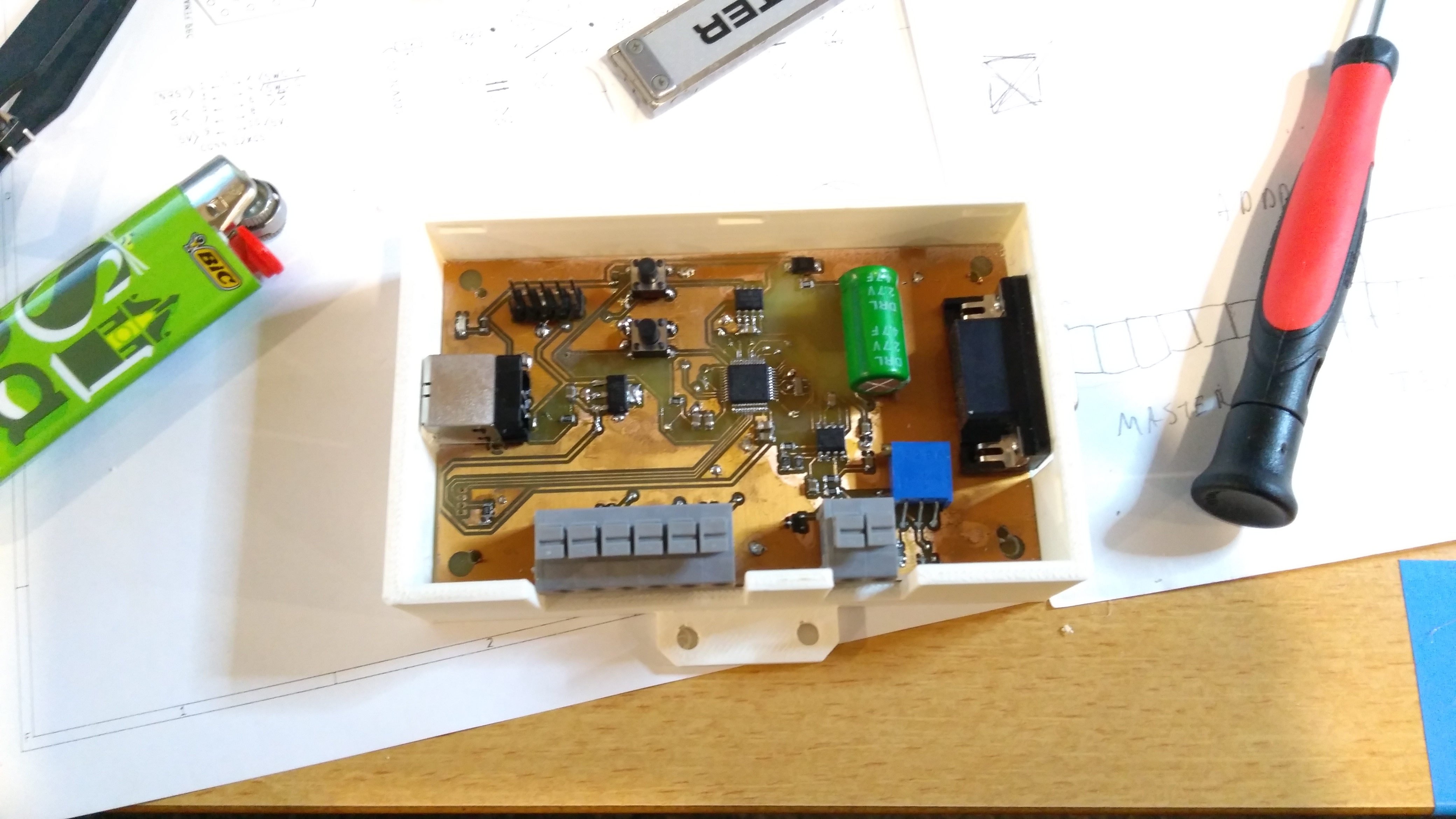
Our design uses relatively cheap irfp260 mosfets instead of special(and expensive) linear rated fets. The ideea is to downrate them enough so they don’t blow up and still be economical compared to the specialty linear fets. We use 8 IRFP260s with each having their own feedback loop using 0.1ohm sense resistors and an opamp. The opamps are driven by a 12bit DAC which is driven by an STM32F103.
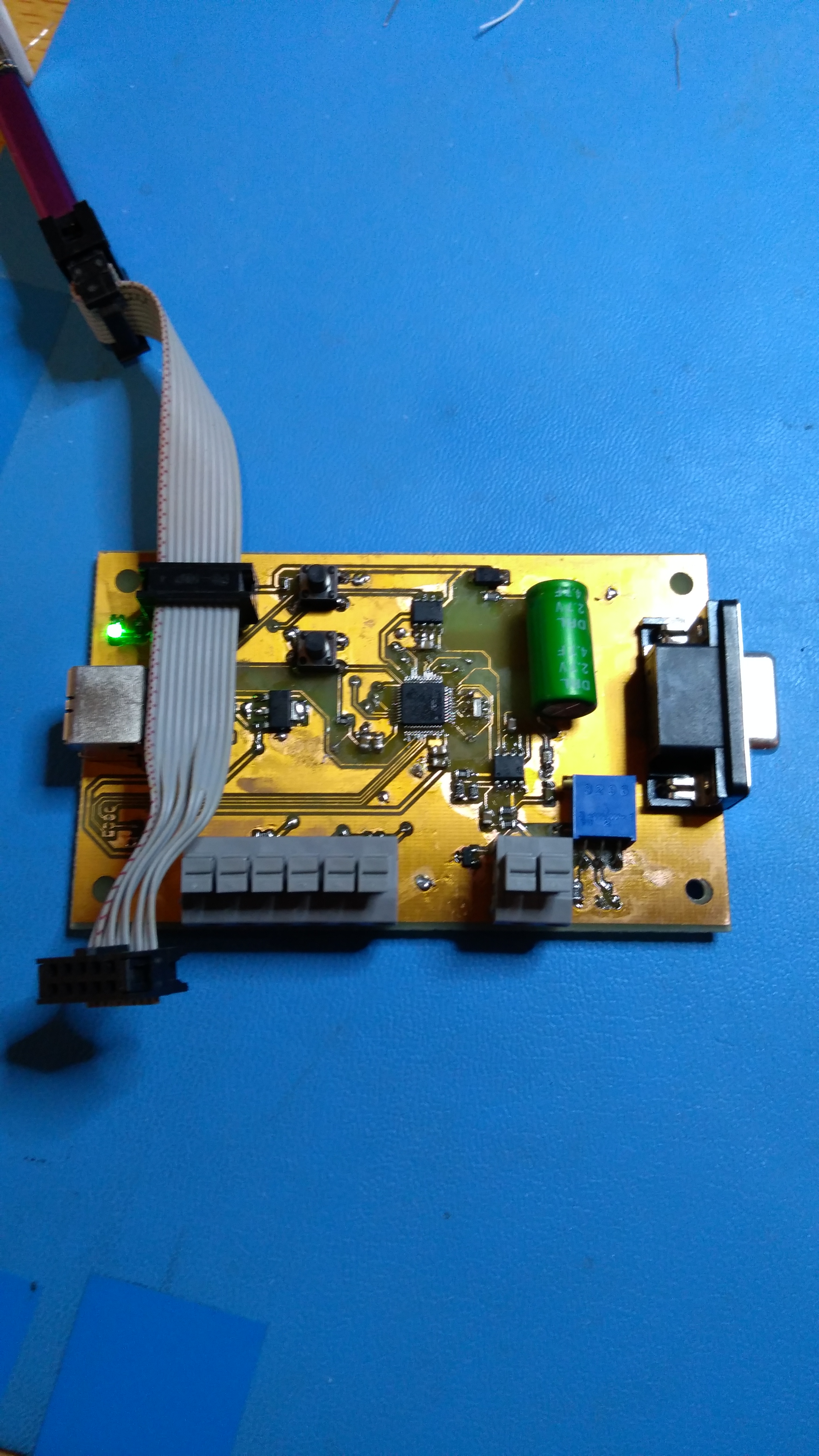
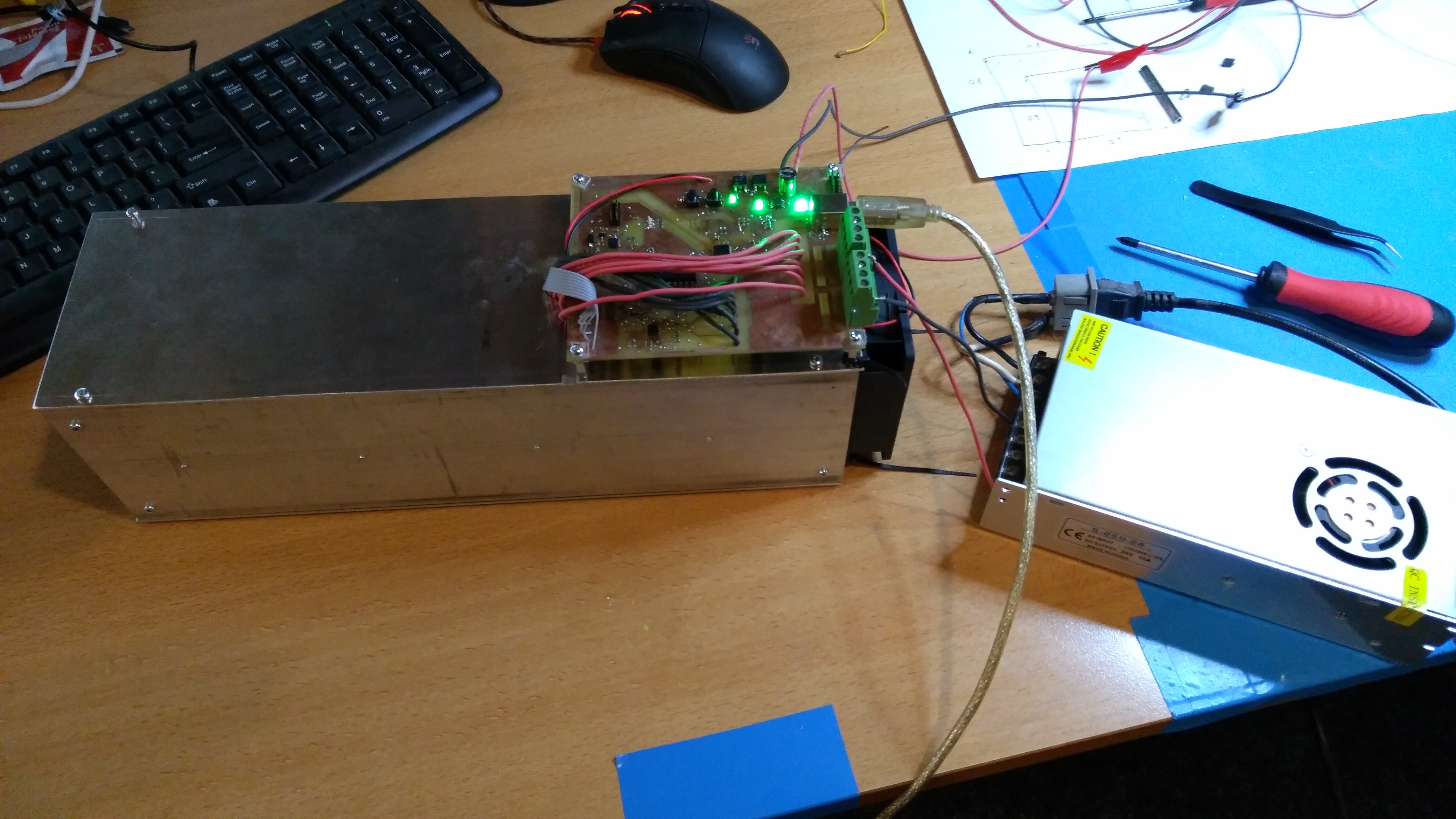
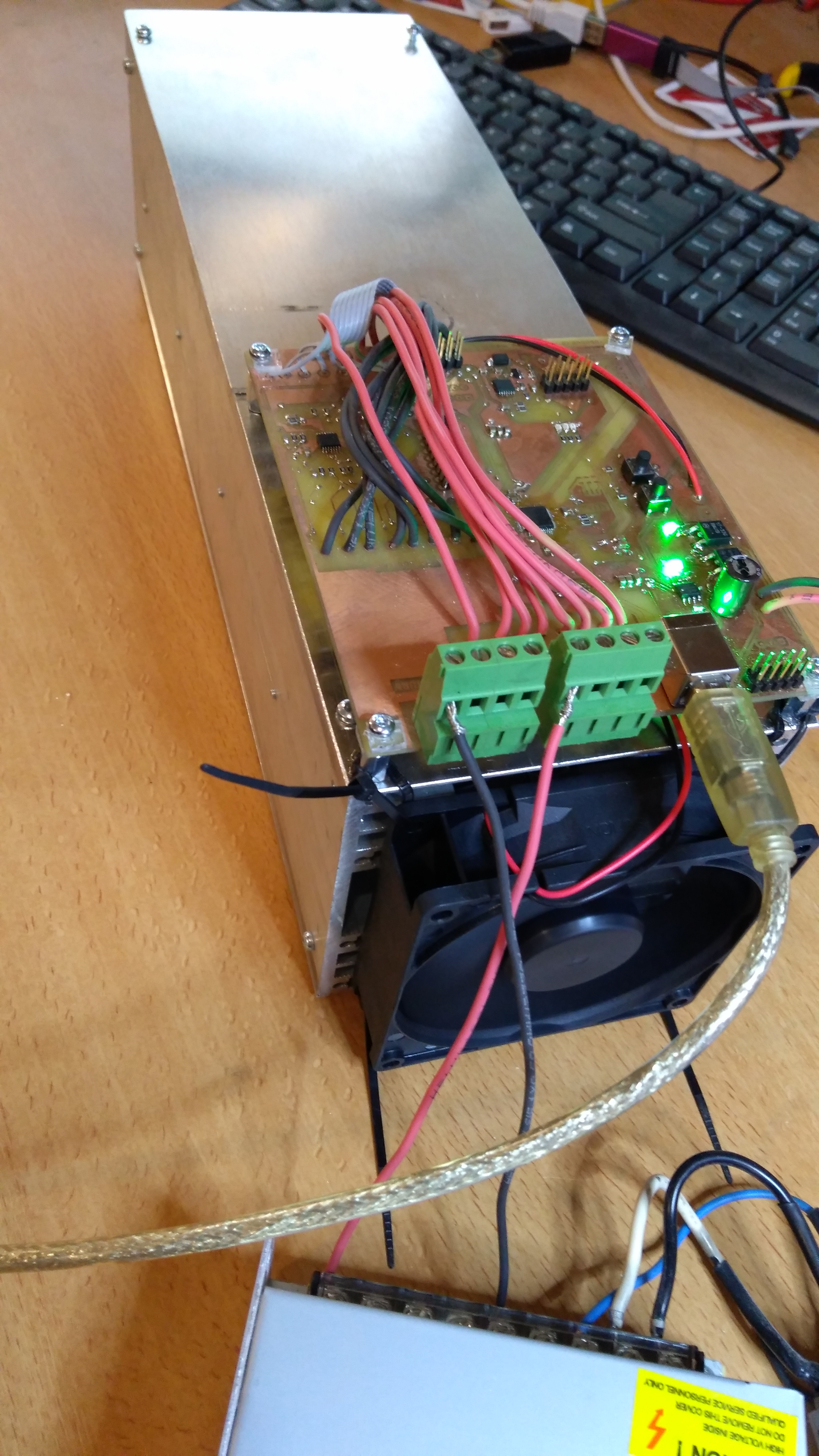
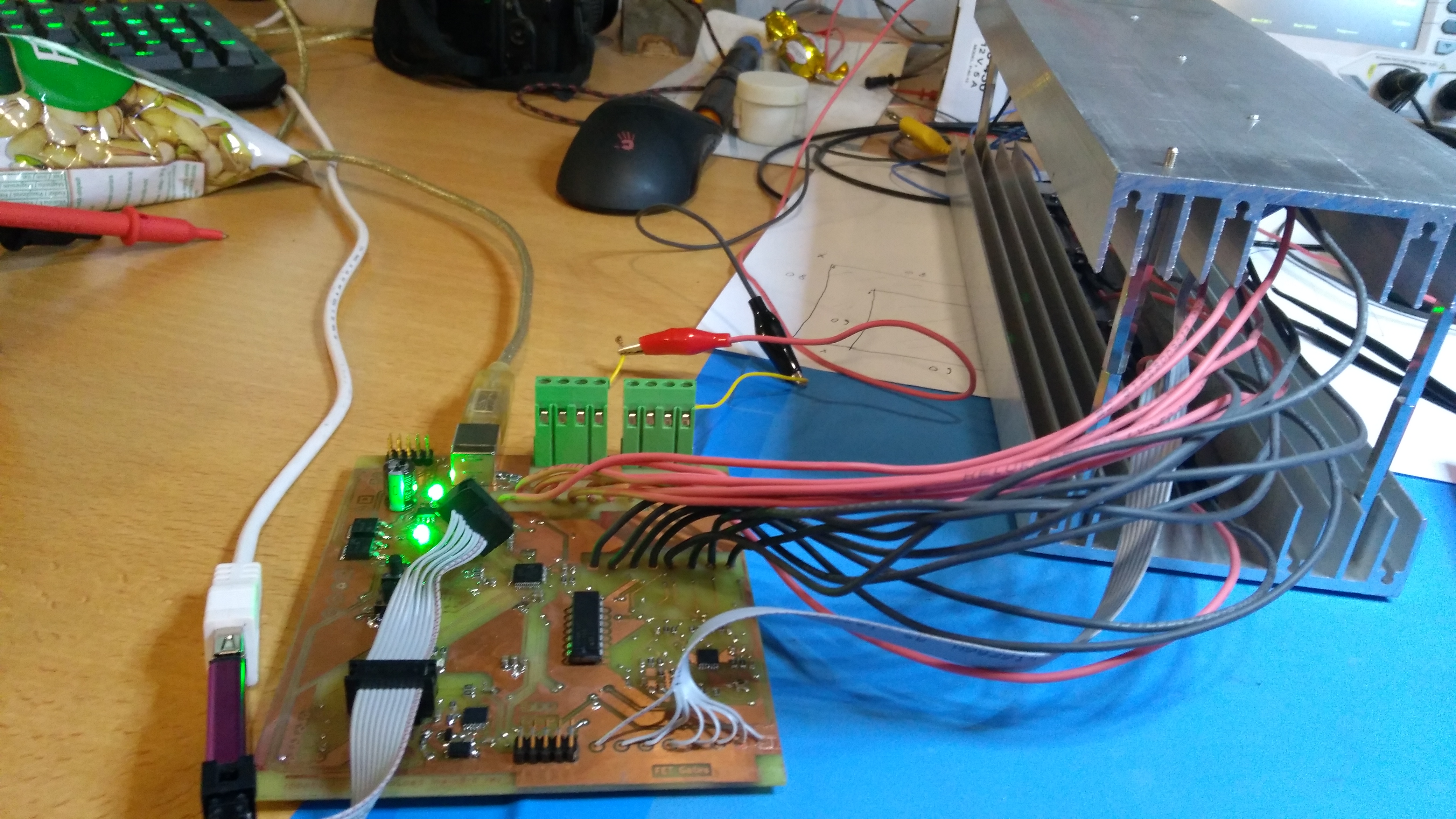
In the pictures you can see the prototype build which is basically just a big heatsink with the control board riding on top of it. The control board has connectors for daisy-chaining more modules and also a connector for hooking up a user interface board – which is the next thing that needs to be built for this proto…
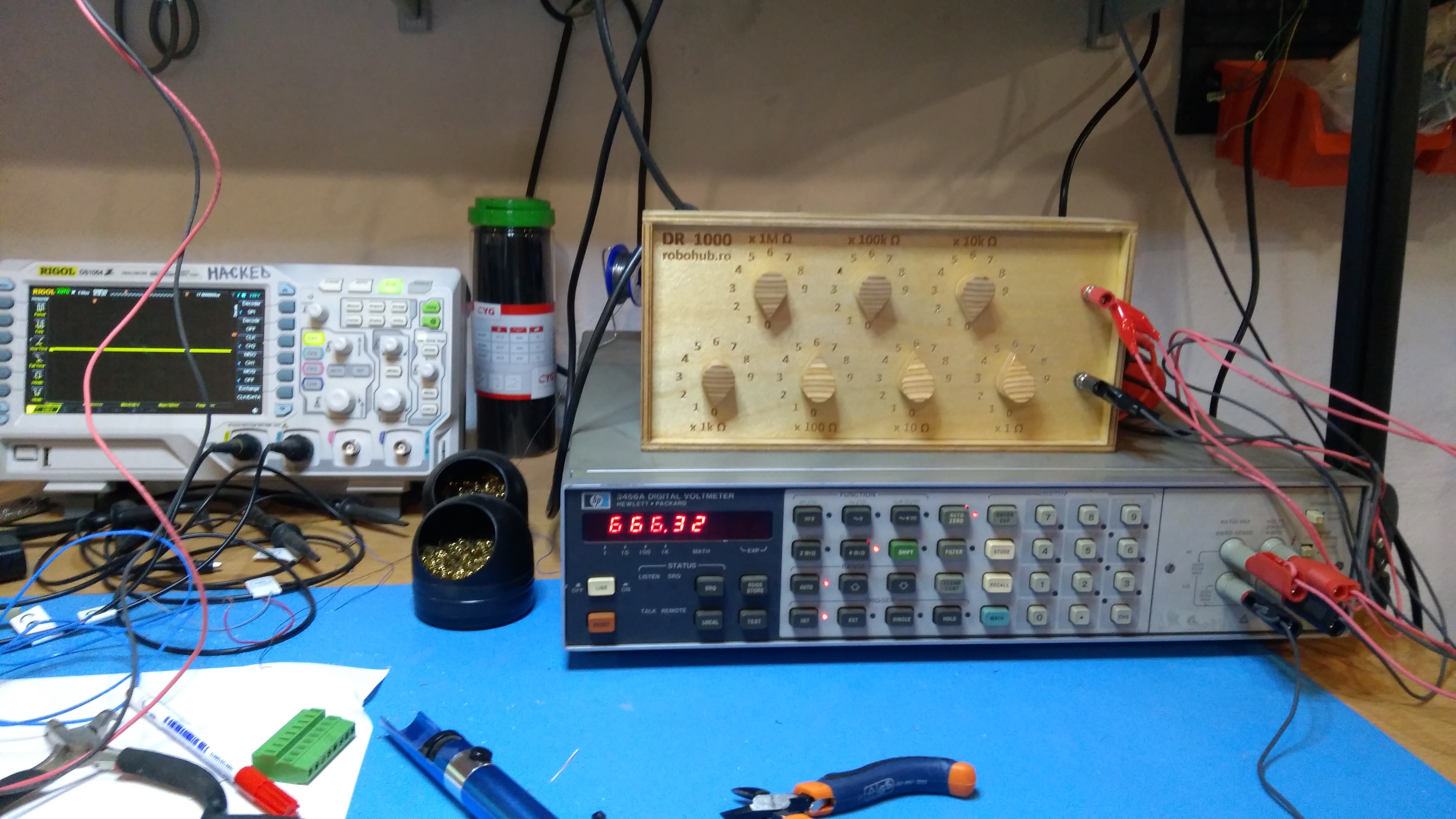
So far I’ve tested this build using a 24V 10A power supply i had lying around and it didn’t break a sweat. The maximum design ratings are 500W@100V or 500W@40A…I’ll have to see if I can get something together to stress test this thing at max load.


Old boat anchor DMM joins the club(HP 3456A)

Old boat anchor DMM joins the club(HP 3456A)

We managed to snatch an old(1983 going by chip date codes) HP 3456A 6.5 digit DMM off ebay recently.
It arrived quickly and well packed from Italy but when I turned it on I was greeted by a display showing 6 dashes instead of a measurement. So I went through the manual to see if I’m being an idiot and don’t know how to use it but it seems like the old beast really did have a problem…
Going through the troubleshooting sections of the manual I learned that if you are presented with the dashes on the display and you run the self test and you DON’T get error -3 then you have to check pin 9 of U17 on board A3 and pin 10 of U13 on board A4…So I opened it up, checked those chips and what do you know? Some cold solder joints on U17. 5 minutes and a bit of solder later and it was back in action!
Check out the photos – I have to say this multimeter is a thing of beauty. It is a truly beautiful design both electronically and mechanically!


64 channel DS18B20 temperature data logger

64 channel DS18B20 temperature data logger

We continue on our temperature related adventures with a whopping 64 channel DS18B20 datalogger…
This is another 100% in-house build(except for the chinese DS18b20 sensors of course).
The basic idea is that these 1-wire sensors can be addressed by a 64 Byte GUID which allows you to hook up as many as you’d like to a single gpio pin. We decided to stop at 2×32 channels for the sake of our sanity.
Apart from measuring temperature, this puppy also has a LEM Hall effect current sensor that is good for -250A to +250A. This is the blue loopy thing and the white box below it contains a 12 bit SPI ADC and a 0.1% initial accuracy 3v3 reference(MCP1501) so you can have a rather long cable run from the MCU to the Hall Sensor(of course, an i2c ADC would’ve been nicer but it’s all we had at hand).
In addition to the current sensor we also gave it a 0-100V DC voltage sense input.
Now, obviously, the smartphone app starts to get a bit crowded with the (now 32) number of sensors this thing can put out. That’s why we built a PC app for logging and graphing which we’ll cover in a different write-up.
Oh, and it all runs off an STM32F103.

Some pictures of the lovely beast.


PT1000 USB Temperature sensor

PT1000 USB Temperature sensor

Here we brag about or USB PT1000 temperature sensor. The board was build in-house(notice the bodge wires) and uses an STM32F0 with integrated USB peripheral to talk to an android phone and report the sensed temperature.
This build measures the resistance of the sensor using a Wheatstone bridge(back of the board). In order to get accurate readings using the bridge we had to calibrate it using our DR1000 decade resistor box in place of the PT1000 simulating a few datapoints and then we fit the resulting curve to a 3rd order polynomial. The end result is quite satisfying and reliable – as long as the PT1000 datasheet doesn’t lie too much. For reference this is the RTD we used: PT1000

This is part of a larger concept that all our devices should have USB connectivity(especially sensors).

Some pictures of the device:


Decade Resistor Box

Decade Resistor Box

Our little CNC mill did a great job on our homemade resistor box and the keithley agrees!
We used 0.1% tolerance, low tempco resistors for a total of 7 decades from 1 ohm on the lowest decade to 1 MΩ on the highest.
The all plywood case features box joints on the corners made on our diy table saw box joint jig.
She has already proven useful in calibrating our USB PT1000 temperature sensors.

Some more glamour shots